Tutorial on Kicad, Solidworks for Quick Prototyping
Hello, fellow students! I’m Son, a beginner in KiCad and SolidWorks. The steps below will help you get familiar with KiCad or SolidWorks quickly. I hope that after following these basic steps, you’ll be able to start building simple prototypes.
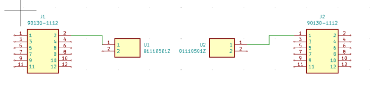
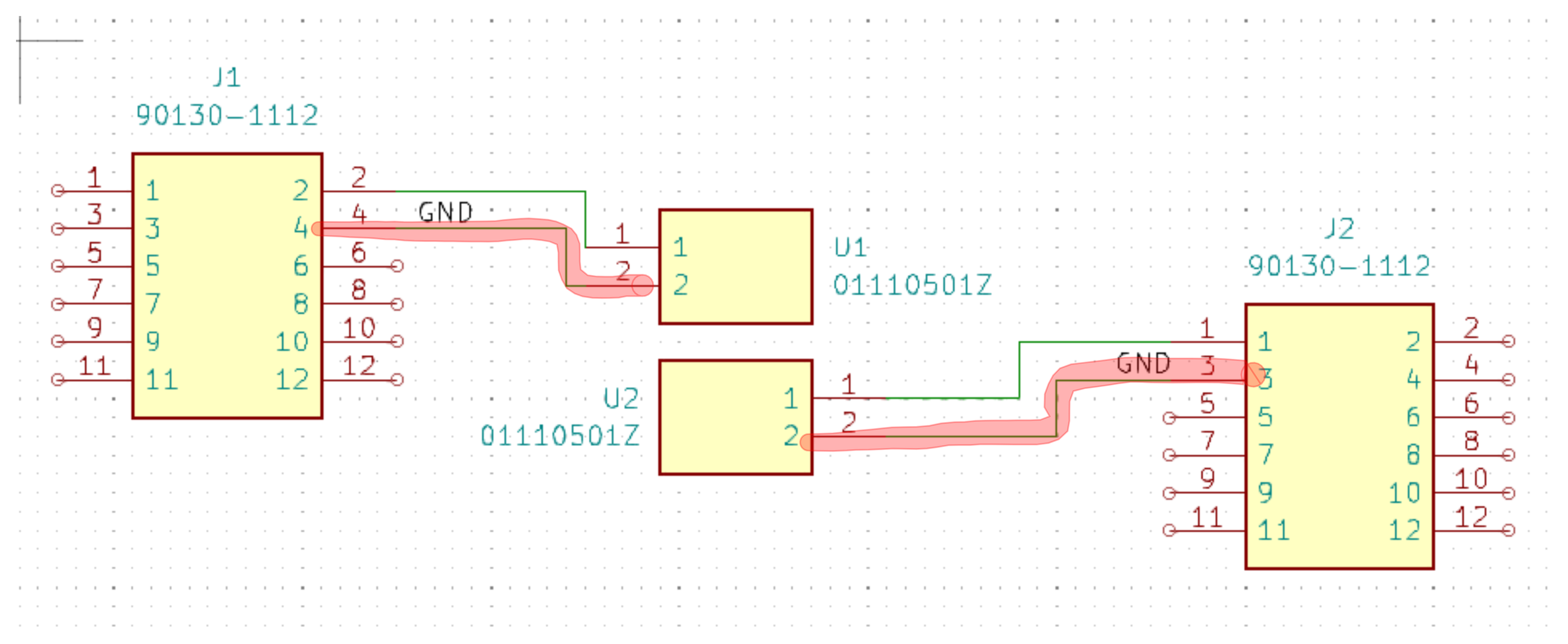
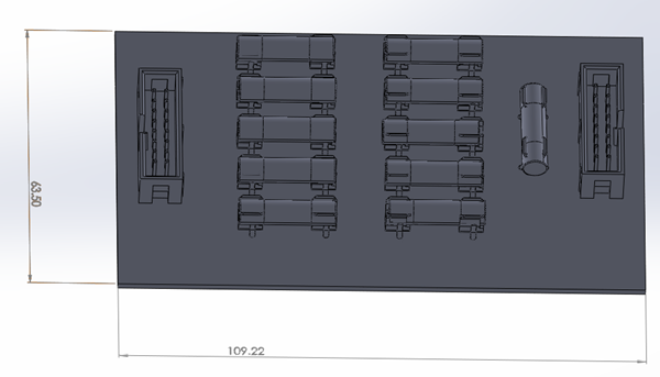
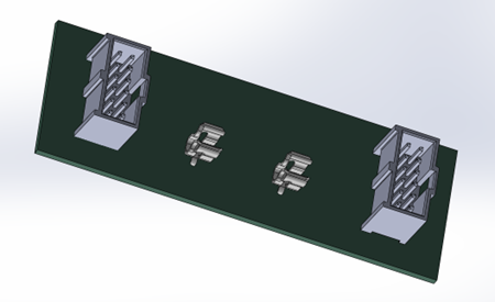
First, we need to define what we’re designing. Our goal is to create a fuse box for voltage sense lines.
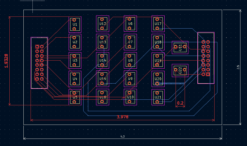
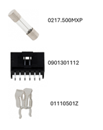
We have a total of 11 sense lines, and each one must have a fuse to protect the end device or downstream device. Our device can handle up to 300mA at peak, so choosing a 500mA fuse seems like a good option.
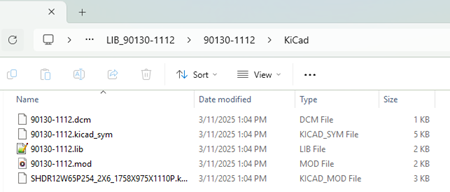
Next, we’ll select a connector and choose the appropriate fuse size along with a suitable fuse holder. Now, let’s go shopping!
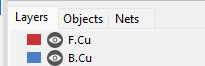
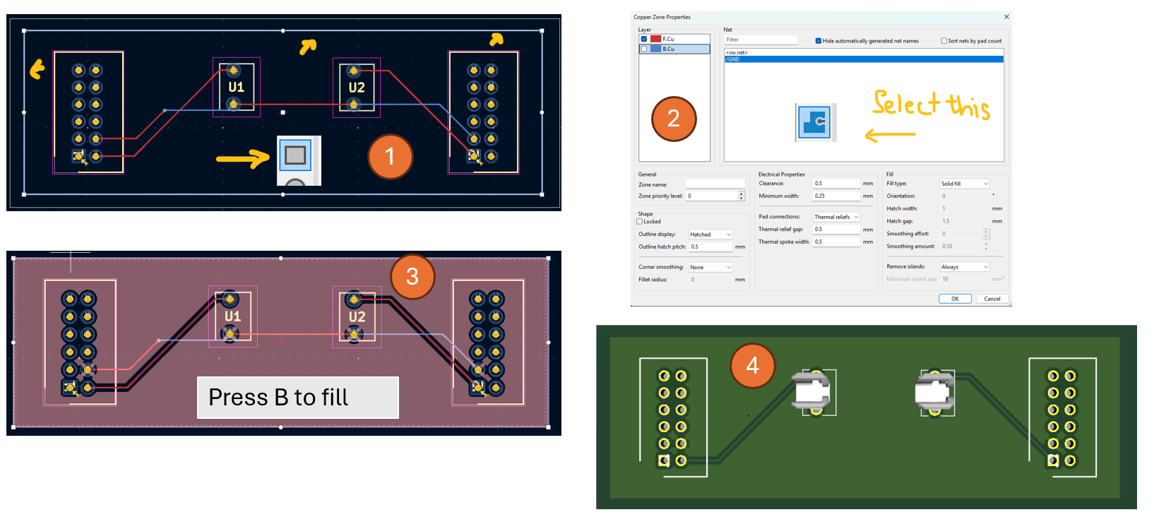
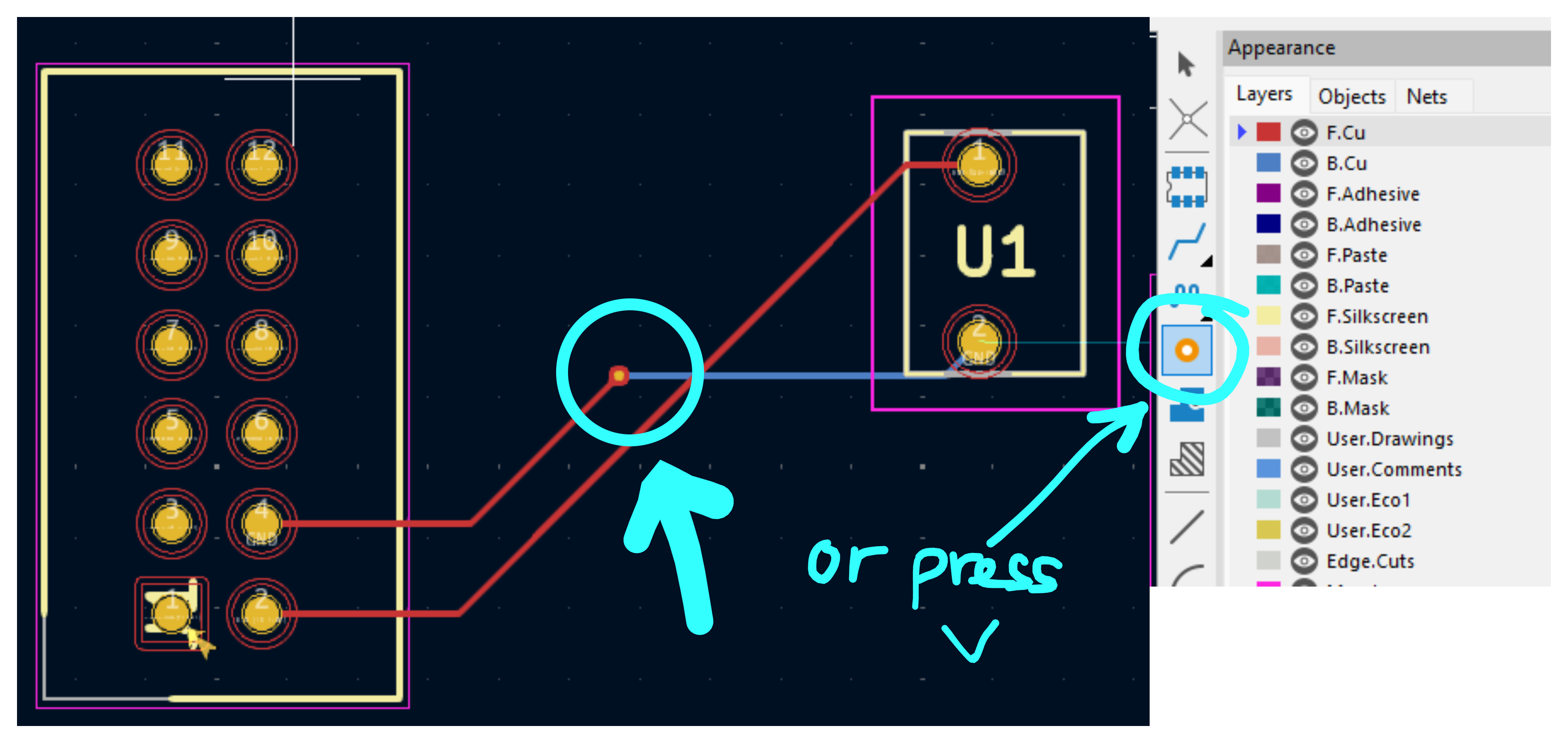
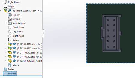
We can also add copper pour which is a copper layer on top of the FR4 to improve signal and dissipate heat. We may don’t need it in this simple circuit.
To draw a rectangular that fills the entire board, I will create a rectangular shape first (1). Then, I will select GND in (2) and then using the rectangular as a guide to draw the boundary. Next, I press B to fill the copper. The final version is shown in (4).
Rotate: using middle button on the mouse
Pan: or moving the design by pressing control button and middle button of the mouse
Spacebar: fit an object into windows
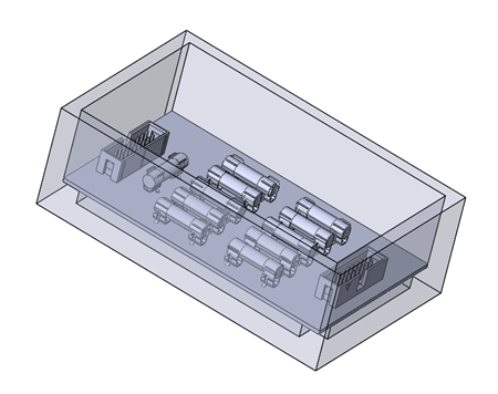
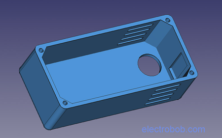
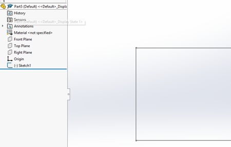
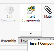
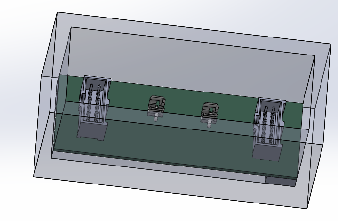
Let build a box for it; I usually search online to get an idea.
The box above looks nice but let make something simple.
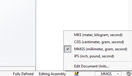
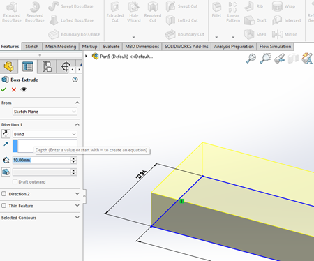
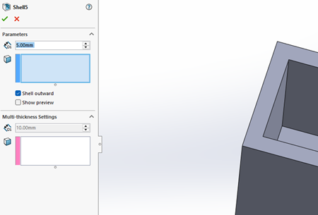
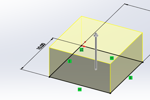
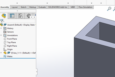
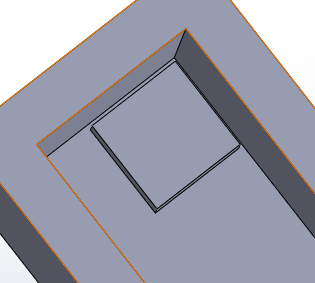
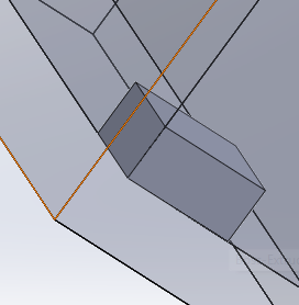
I want to create a box with 5mm thick and cover the pcb board. The box should have 4 leg with the height of 5mm to raise the board up.
The box will be 40mm height.